Altair 8800c Build
Intro

Clock Speed: 2 MHz
Memory: 256 bytes (expandable up to 64 KB)
Bus: S-100 bus
Input/Output: Front panel switches
LED indicators for output
Optional serial and parallel ports
Storage: Optional paper tape reader
Cassette tape interface (add-on)
Altair FDC+ floppy disk controller (add-on)
Expansion Slots: 9 S-100 bus slots (depends on the used Backplane)
Power Supply: 8V DC and +/-16V DC outputs
1x Mean Well HRP-75-7.5 (8V)
1x Mean Well RS-15-15 (+/-16V)
Operating System: None initially; later supported various OS including CP/M
Operating System: None initially; later supported various OS including CP/M
In the realm of personal computing, few machines hold as iconic a status as the Altair 8800. Launched in January 1975 by Micro Instrumentation and Telemetry Systems (MITS), the Altair 8800 is often heralded as the spark that ignited the personal computer revolution.
This groundbreaking device, with its striking array of switches and blinking LED lights, offered computer enthusiasts an unprecedented level of control and customization. Designed initially as a kit for hobbyists and featured on the cover of Popular Electronics, the Altair 8800's appeal extended far beyond its target audience, capturing the imagination of tech visionaries and paving the way for the personal computers that followed.
S-100 Extension Boards
The S-100 bus, introduced alongside the Altair 8800 in 1975, quickly became the de facto standard for early personal computers. Named for its 100-pin edge connector, this robust and versatile bus system enabled users to expand and customize their machines with a wide array of peripheral cards, including memory expansion, input/output interfaces, and storage solutions.
- Connector: 100-pin edge connector
- Bus Width: 8-bit (later expanded to 16-bit with additional lines)
- Power Supply: +8V, +16V, -16V (later +5V, ±12V with updated standards)
- Bus Protocol: Asynchronous with handshake signaling for data transfers
- The bi-directional 8-bit data bus of the Intel 8080 is split into two unidirectional 8-bit data buses. The processor could use only one of these at a time.
Bus Pin Designations and Layout

Altair 8800 CPU Revision 1 (CPU Board)
This board has the distinction as being the first S-100 board ever designed. The layout of the board with its pinout from the 8080 CPU essentially defined the function of the S-100 bus pins.

 |
| MITS 8080 CPU Card |
Clock Signal (Phi1 & Phi2)
For the Intel 8080 to run reliably, it requires a stable, accurate clock signal. Achieving this precision starts with selecting the right 74-series logic ICs (SN7404, SN74123 and SN7406 in TTL) in the clock circuit, ensuring consistent timing and optimal performance for your system.
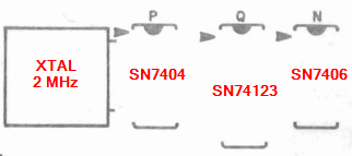 |
| 8800 CPU Board: Clock Circuit |
Avoid using SN74LS (Low Power Schottky) modules. While they may produce a barely acceptable signal for the CPU under certain conditions, they’re notoriously unreliable at startup—and might never properly initialize at all.
 |
| Intel 8080 |
 |
| 74 (TTL) |
Timings
 |
| Þ₁ Pulse Width (min. 60ns) |
 |
| Þ₂ Pulse Width (min. 220ns) |
 |
| Delay Þ₁ to Þ₂ (Leading Edges, min. 80ns) |
 |
| Delay Þ₂ to Þ₁ (min. 70ns) |
 |
| Clock Period (min. 480ns, max. 2000ns) |
Front Panel
The Altair 8800c front panel board set is a drop-in replacement for the original Altair 8800 front panel board.
 |
| Front Panel Board (front) |
 |
| Front Panel Board (back) |
 |
| Front with inserted switches |
 |
| Front with installed LED's and switches |
 |
| Finished Front |
Front Panel Interface Board
 |
| Front Panel Interface Board |
To run the board in the right way you need a programmed PIC16F1828 with startup and self-programming code and the Firmware as well.
FDC+
The Altair FDC+ is an enhanced version of the original MITS 8" floppy disk controller for the Altair 8800. The FDC+ is a 100% compatible drop-in replacement for the original two-board Altair FDC. The FDC+ can serve as a replacement for a missing or defective Altair FDC, or you can use the FDC+ as a reference point while restoring original floppy equipment to working condition.
In addition to providing disk controller functions, the FDC+ includes up to 64K of RAM and 8K of PROM that can be separately enabled if needed.
 |
| FDC+ Board |
Build in Monitor
The FDC+ board has a build in Monitor where you can change the Baudrate or do Firmware updates. It can be activate at the Drv Type switch on the FDC+ board:
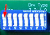
The far left switch on the Drive Type switch bank is labeled “Mon.” If this switch is set to 1 (rocker down towards the top of the board), the monitor is entered upon power up.
 |
| FDC+ Monitor |
Serial Drive Server
To emulate an Altair Floppy drive over the Serial port you need to set the drive type to 111 (6) on the Drv Type Switch. Performance of the serial drive is virtually identical to the original Altair floppy drives.
 |
| Drv Type 111 |
Built in RAM
This card can provide the full size addressable memory of 64KB but can be configured to have less if needed (the top 256 Bytes of RAM are not available):
 |
| RAM Switch Position for 64KB and Enabled |
Built in PROM
It's a 27C64 EPROM with 8KB of size.
Pre-programmed content of PROM when shipped:
FF00: Combined Disk Boot Loader (CDBL)
FE00: Altair Multi-Boot Loader (MBL, boots cassette tapes, paper tapes)
FD00: Altair Turnkey Monitor (TURMON)
FC00: Intel Hex file loader
F800: Altair Monitor (ALTMON)
To start from FF00 to use the Combined Disk Boot Loader use this DIP switch settings:
 |
| PROM enabled and start at FF00 |
The switches labeled “12” to “8” correspond to address lines A12 to A8 and are used to select the 256 byte page within the 8K PROM at which the PROM begins to respond.
88-2SIOJP
 |
| Dual Serial board with Jump-Start and PROM |
The 88-2SIOJP is an enhanced dual serial port board designed for the MITS Altair and compatible computers.
Functions:
- Two serial ports that are software and hardware compatible with the MITS 88-2SIO, with some important enhancements
- One EPROM/EEPROM socket, providing 2K-bytes to 16K-bytes of nonvolatile storage, with write capability for EEPROMs
- Options for either MITS ROM Basic or Amon (a full-feature ROM monitor that includes all MITS loaders)
- Power-on/reset jump-start that is compatible with memory boards
- Improved power-on clear circuit, eliminating the need to toggle the Stop and Reset switches on the Altair 8800 and 8800a
- Compatible with both 8080 and Z-80 CPU boards, up to 4 MHz
- Optional support for computers with no front panel ("Turnkey" computers)
Serial Ports
The serial ports are designed around the Motorola 68A50 or 68B50 ACIA, faster versions of the same communications chip used in the MITS 88- 2SIO. The data rate for each serial port is set by a DIP switch, allowing communication from 110 baud through 38.4K (76.8K baud with the 68B50).
- Port 0: to connect a Terminal or Terminal Emulator
- Port 1: to transfer Files/Data
Switch Settings
- SW1: Jumpstart address: e.g. FF00 for CDBL in FDC+ PROM => 11111111 0 (Enable)
- SW2: Sense Switch Register (all open for non Turnkey computers => 111111111)
- SW3: Serial Port Address => <6:1> 000100 <7> 0 (for 8080), <8> 0 (Use Phantom)
- SW4: EPROM Address => <5:1> 11111, <8:6> 001 (4K for Amon), <9> 0 Auto-Disable
- SW5: Port 0 baud rate (suggested 9600 -> pin 4 closed)
- SW6: Port 1 baud rate (suggested 9600 -> pin 4 closed)
Booting into CP/M
Set the Jumpstart address to FF00, and activate the Auto disable EPROM feature to jump into the Combined Disk Boot Loader from the FDC+ PROM. After depressing RUN the CDBL loads a disk from the floppy (or the loaded dsk image from the FDC+Serial Drive Server).
Connect a Terminal with the Serial Port
To connect a terminal to the serial port connected to the 88-2SIOJP card the screen command (VT100/ANSI terminal emulation) can be used:
e.g. screen /dev/tty.usbserial-FT862T3S0 9600 (Ctrl-a k to exit)
 |
CP/M-80 2.2b, 56K variant |

Kommentare
Kommentar veröffentlichen